গোপনীয়তার বিবৃতি: আপনার গোপনীয়তা আমাদের কাছে অত্যন্ত গুরুত্বপূর্ণ। আমাদের সংস্থা আপনার ব্যক্তিগত তথ্যগুলি আপনার সুস্পষ্ট অনুমতিগুলি সহ কোনও এক্সপ্যানিতে প্রকাশ না করার প্রতিশ্রুতি দেয়।
মডেল নাম্বার.: NSO4GU3AB
পরিবহন: Ocean,Air,Express,Land
শোধের ধরণ: L/C,T/T,D/A
ইনকোটার্ম: FOB,EXW,CIF
4 জিবি 1600 এমএইচজেড 240-পিন ডিডিআর 3 ইউডিআইএমএম
পরিবর্ধন ও পরিবর্তন তালিকা
|
Revision No. |
History |
Draft Date |
Remark |
|
1.0 |
Initial Release |
Apr. 2022 |
|
![]()
অর্ডার তথ্য টেবিল
|
Model |
Density |
Speed |
Organization |
Component Composition |
|
NS04GU3AB |
4GB |
1600MHz |
512Mx64bit |
DDR3 256Mx8 *16 |
বর্ণনা
হেনগস্টার আনহাফারড ডিডিআর 3 এসডিআরএম ডিআইএমএমএস (আনহাফারড ডাবল ডেটা রেট সিঙ্ক্রোনাস ড্রাম ডুয়াল ইন-লাইন মেমরি মডিউল) হ'ল কম শক্তি, উচ্চ-গতির অপারেশন মেমরি মডিউলগুলি যা ডিডিআর 3 এসডিআরএম ডিভাইস ব্যবহার করে। NS04GU3AB একটি 512 মি x 64-বিট দুটি র্যাঙ্ক 4 জিবি ডিডিআর 3-1600 সিএল 11 1.5 ভি এসডিআরএএম আনহফারড ডিআইএমএম পণ্য, ষোল 256 মি x 8-বিট এফবিজিএ উপাদানগুলির উপর ভিত্তি করে। এসপিডি জেডেক স্ট্যান্ডার্ড লেটেন্সি ডিডিআর 3-1600 সময় 11-11-11 সময় 1.5V এ প্রোগ্রাম করা হয়। প্রতিটি 240-পিন ডিআইএমএম সোনার যোগাযোগের আঙ্গুলগুলি ব্যবহার করে। পিসি এবং ওয়ার্কস্টেশনগুলির মতো সিস্টেমে ইনস্টল করার সময় এসডিআরএএম আনহাফার্ড ডিআইএমএম প্রধান মেমরি হিসাবে ব্যবহারের উদ্দেশ্যে তৈরি।
বৈশিষ্ট্য
- পাওয়ার সরবরাহ: ভিডিডি = 1.5V (1.425V থেকে 1.575V)
vddq = 1.5V (1.425V থেকে 1.575V)
1600 এমবি/সেকেন্ড/পিনের জন্য 800 এমএইচজেড এফসি কে
8 স্বতন্ত্র অভ্যন্তরীণ ব্যাংক
- প্রোগ্রামেবল সিএএস বিলম্ব: 11, 10, 9, 8, 7, 6
- প্রোগ্রামেবল অ্যাডিটিভ লেটেন্সি: 0, সিএল - 2, বা সিএল - 1 ঘড়ি
8-বিট প্রাক-খাওয়ানো
বার্স্ট দৈর্ঘ্য: 8 (কোনও সীমা ছাড়াই ইন্টারলিভ করুন, কেবলমাত্র "000" শুরু করার ঠিকানা দিয়ে ক্রমিক), 4 টিসিসিডি = 4 সহ যা বিরামবিহীন পড়তে বা লেখার অনুমতি দেয় না [হয় এ 12 বা এমআরএস ব্যবহার করে ফ্লাইতে]
-বিআই-দিকনির্দেশক ডিফারেনশিয়াল ডেটা স্ট্রোব
Intern অভ্যন্তরীণ (স্ব) ক্রমাঙ্কন; জেডকিউ পিনের মাধ্যমে অভ্যন্তরীণ স্ব -ক্রমাঙ্কন (আরজেডকিউ: 240 ওহম ± 1%)
OD ওডিটি পিন ব্যবহার করে ডাই টার্মিনেশন
Ta
- এসিঙ্ক্রোনাস রিসেট
-অ্যাডজাস্টেবল ডেটা-আউটপুট ড্রাইভ শক্তি
-ফ্লাই বাই টপোলজি
-পিসিবি: উচ্চতা 1.18 "(30 মিমি)
RORHS অনুগত এবং হ্যালোজেন মুক্ত
মূল সময় পরামিতি
|
MT/s |
tRCD(ns) |
tRP(ns) |
tRC(ns) |
CL-tRCD-tRP |
|
DDR3-1600 |
13.125 |
13.125 |
48.125 |
2011/11/11 |
ঠিকানা টেবিল
|
Configuration |
Refresh count |
Row address |
Device bank address |
Device configuration |
Column Address |
Module rank address |
|
4GB |
8K |
32K A[14:0] |
8 BA[2:0] |
2Gb (256 Meg x 8) |
1K A[9:0] |
2 S#[1:0] |
পিন বর্ণনা
|
Symbol |
Type |
Description |
|
Ax |
Input |
Address inputs: Provide the row address for ACTIVE commands, and the column |
|
BAx |
Input |
Bank address inputs: Define the device bank to which an ACTIVE, READ, WRITE, or |
|
CKx, |
Input |
Clock: Differential clock inputs. All control, command, and address input signals are |
|
CKEx |
Input |
Clock enable: Enables (registered HIGH) and disables (registered LOW) internal circuitry |
|
DMx |
Input |
Data mask (x8 devices only): DM is an input mask signal for write data. Input data is |
|
ODTx |
Input |
On-die termination: Enables (registered HIGH) and disables (registered LOW) |
|
Par_In |
Input |
Parity input: Parity bit for Ax, RAS#, CAS#, and WE#. |
|
RAS#, |
Input |
Command inputs: RAS#, CAS#, and WE# (along with S#) define the command being |
|
RESET# |
Input |
Reset: RESET# is an active LOW asychronous input that is connected to each DRAM and |
|
Sx# |
Input |
Chip select: Enables (registered LOW) and disables (registered HIGH) the command |
|
SAx |
Input |
Serial address inputs: Used to configure the temperature sensor/SPD EEPROM address |
|
SCL |
Input |
Serial |
|
CBx |
I/O |
Check bits: Used for system error detection and correction. |
|
DQx |
I/O |
Data input/output: Bidirectional data bus. |
|
DQSx, |
I/O |
Data strobe: Differential data strobes. Output with read data; edge-aligned with read data; |
|
SDA |
I/O |
Serial |
|
TDQSx, |
Output |
Redundant data strobe (x8 devices only): TDQS is enabled/disabled via the LOAD |
|
Err_Out# |
Output (open |
Parity error output: Parity error found on the command and address bus. |
|
EVENT# |
Output (open |
Temperature event: The EVENT# pin is asserted by the temperature sensor when critical |
|
VDD |
Supply |
Power supply: 1.35V (1.283–1.45V) backward-compatible to 1.5V (1.425–1.575V). The |
|
VDDSPD |
Supply |
Temperature sensor/SPD EEPROM power supply: 3.0–3.6V. |
|
VREFCA |
Supply |
Reference voltage: Control, command, and address VDD/2. |
|
VREFDQ |
Supply |
Reference voltage: DQ, DM VDD/2. |
|
VSS |
Supply |
Ground. |
|
VTT |
Supply |
Termination voltage: Used for control, command, and address VDD/2. |
|
NC |
– |
No connect: These pins are not connected on the module. |
|
NF |
– |
No function: These pins are connected within the module, but provide no functionality. |
নোট : নীচের পিন বিবরণ সারণীটি সমস্ত ডিডিআর 3 মডিউলগুলির জন্য সমস্ত সম্ভাব্য পিনের একটি বিস্তৃত তালিকা। সমস্ত পিন তালিকাভুক্ত মে এই মডিউলটিতে সমর্থন করা হবে না। এই মডিউলটির জন্য নির্দিষ্ট তথ্যের জন্য পিন অ্যাসাইনমেন্টগুলি দেখুন।
কার্যকরী ব্লক ডায়াগ্রাম
4 জিবি, 512 এমএক্স 64 মডিউল (এক্স 8 এর 2 র্যাঙ্ক)


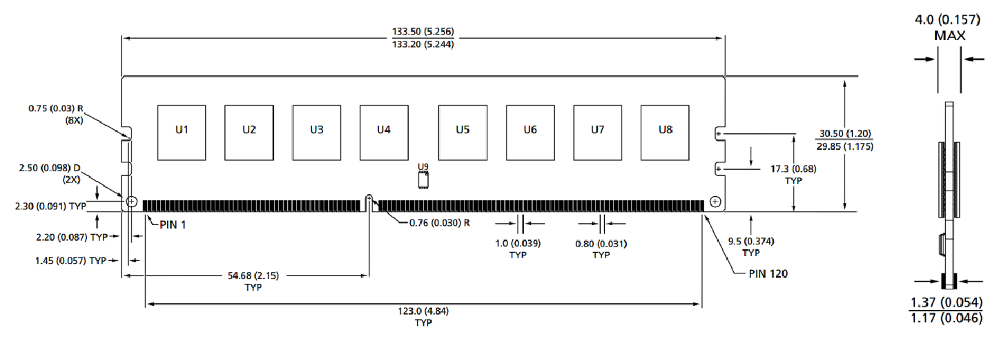
মডিউল মাত্রা
সামনের দিক

সামনের দিক

মন্তব্য:
1. সমস্ত মাত্রা মিলিমিটারে (ইঞ্চি); সর্বাধিক/মিনিট বা সাধারণ (টাইপ) যেখানে উল্লেখ করা হয়েছে।
2. অন্যথায় নির্দিষ্ট না করা পর্যন্ত সমস্ত মাত্রায় ± 0.15 মিমি উপর আলোচনা।
3. মাত্রিক চিত্রটি কেবল রেফারেন্সের জন্য।
পণের ধরন : শিল্প স্মার্ট মডিউল আনুষাঙ্গিক


গোপনীয়তার বিবৃতি: আপনার গোপনীয়তা আমাদের কাছে অত্যন্ত গুরুত্বপূর্ণ। আমাদের সংস্থা আপনার ব্যক্তিগত তথ্যগুলি আপনার সুস্পষ্ট অনুমতিগুলি সহ কোনও এক্সপ্যানিতে প্রকাশ না করার প্রতিশ্রুতি দেয়।

আরও তথ্য পূরণ করুন যাতে আপনার সাথে দ্রুত যোগাযোগ করতে পারে
গোপনীয়তার বিবৃতি: আপনার গোপনীয়তা আমাদের কাছে অত্যন্ত গুরুত্বপূর্ণ। আমাদের সংস্থা আপনার ব্যক্তিগত তথ্যগুলি আপনার সুস্পষ্ট অনুমতিগুলি সহ কোনও এক্সপ্যানিতে প্রকাশ না করার প্রতিশ্রুতি দেয়।